In this demo, I built a mid-scale enterprise network protected by a Check Point R80.40 deployment. The objective was not only to install and configure the platform, but also to demonstrate how enterprise firewalls handle modern traffic inspection, centralized management, NAT, and application-aware filtering techniques such as SNI-based access control.
The environment was deployed completely in GNS3 using official Check Point images for the Security Gateway, Management Server, and Smart Console components.
The final topology simulated a realistic enterprise infrastructure containing:
- Multiple VLAN segments
- Internal enterprise services
- Branch-style connectivity
- Internet edge routing
- Centralized security enforcement
- NAT configuration
- HTTPS inspection
- SNI-based filtering policies
- Application-aware traffic inspection
The demo highlights how Check Point separates centralized management functionality from real-time traffic enforcement while providing granular visibility into enterprise traffic flows.
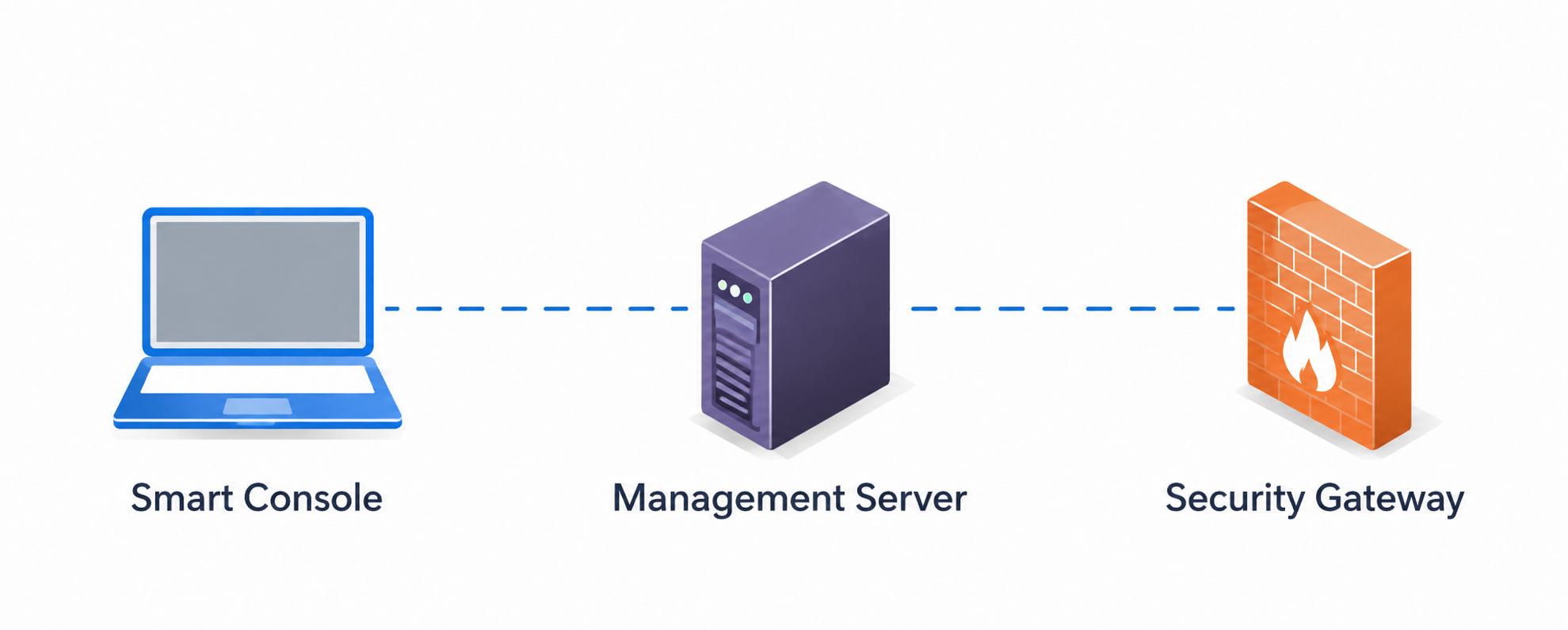
One of the first things that becomes clear when working with Check Point is that the architecture is highly modular. Instead of configuring everything directly on the firewall itself, the platform separates management operations from traffic processing.
The deployment is mainly built around three major components:
- Smart Console
- Management Server
- Security Gateway
This separation allows administrators to centrally manage security policies while gateways focus on packet inspection and enforcement.
Smart Console
The Smart Console acts as the administrative interface of the platform. It is the graphical management application used to configure:
- Firewall policies
- NAT rules
- Network objects
- Threat prevention settings
- Logging and monitoring
- VPN configuration
- Application filtering rules
The Smart Console itself does not process traffic. Instead, it communicates with the Management Server, where all configurations and policies are stored centrally.
This architecture becomes particularly useful in enterprise environments where multiple gateways need to be managed consistently from a single interface.
At a high level, the Smart Console can be viewed as the operational management plane of the Check Point ecosystem.
Management Server
The Management Server is the central control component of the architecture. All firewall rules, NAT configurations, objects, logging data, VPN settings, and security policies are stored here.
When an administrator modifies a policy from the Smart Console, the changes are first written to the Management Server database. However, the new configuration is not immediately enforced on the gateway.
Check Point uses a publish-and-install workflow:
- Publish stores the configuration changes in the management database
- Install Policy pushes the compiled policy package to the Security Gateway
This separation is important because it allows administrators to review and validate changes before they impact production traffic.
The Management Server also maintains communication with gateways using Secure Internal Communication (SIC).
Security Gateway
The Security Gateway is the actual firewall responsible for traffic enforcement and packet inspection.
All packets entering or leaving the enterprise network traverse the gateway, where security policies are enforced in real time.
The gateway handles functions such as:
- Stateful inspection
- NAT translation
- URL filtering
- Application control
- Threat prevention
- IPS/IDS processing
- HTTPS inspection
In this demo, the gateway was deployed as the primary edge security device between the internal enterprise network and the external Internet cloud.
The gateway simultaneously performed routing, NAT, and security enforcement operations.
Secure Internal Communication (SIC)
Communication between the Management Server and the Security Gateway uses the Secure Internal Communication (SIC) protocol.
SIC establishes a trusted relationship between the gateway and the management server using certificate-based authentication and encrypted communication channels.
Without SIC initialization, the Management Server cannot securely manage or push policies to the gateway.
During deployment, SIC establishment was one of the first configuration steps after assigning management IP addresses and defining administrator credentials.
This trust relationship forms the foundation of the distributed Check Point architecture.
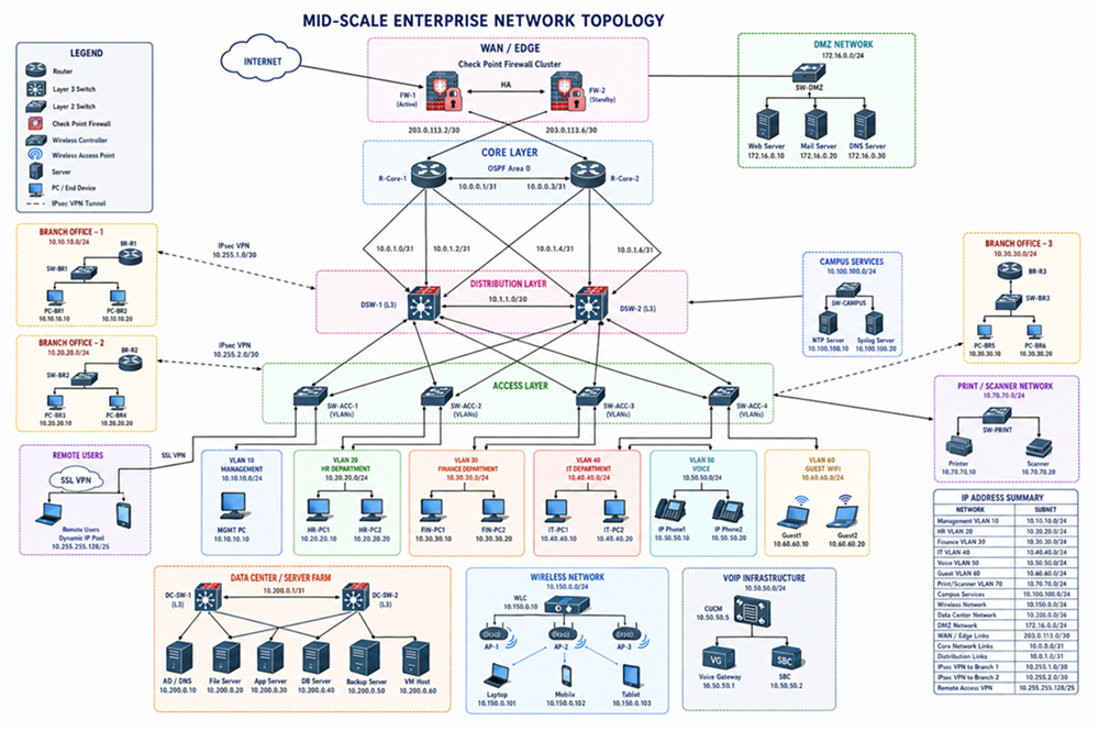
Enterprise Network Topology
The topology included:
- Core and access switching layers
- Multiple VLANs
- Internal enterprise hosts
- Service segmentation
- Branch-style connectivity
- Internet edge routing
- Centralized firewall inspection
Separate VLANs were created for management traffic, user traffic, and internal services.
The Security Gateway sat at the enterprise edge and enforced all security policies before traffic was forwarded toward external networks.
NAT Configuration
After deployment, NAT was configured on the gateway to provide Internet connectivity for internal hosts.
The gateway translated private internal addresses into externally routable addresses before forwarding traffic to the Internet.
This allowed enterprise devices to:
- Access external websites
- Resolve DNS queries
- Communicate securely with Internet services
- Maintain internal address isolation
The NAT configuration also enabled controlled outbound access while preserving enterprise network segmentation.
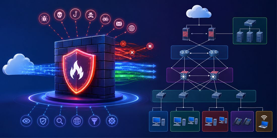
Firewall Policy and Traffic Inspection
The primary security objective of this demo was to experiment with application-aware filtering techniques instead of relying only on traditional IP- and port-based filtering.
Modern web traffic is increasingly encrypted, which reduces the effectiveness of Layer 3 and Layer 4 filtering alone.
To address this, policies were implemented using:
- SNI inspection
- HTTPS header analysis
- Domain-based filtering
- Selective HTTPS interception
SNI-Based Filtering
Server Name Indication (SNI) is part of the TLS handshake and exposes the destination hostname requested by the client before encryption is fully established.
This allows the firewall to identify the intended domain even when HTTPS encryption is being used.
In this demo, the gateway was configured to:
- Allow or deny access based on SNI values
- Detect requests to specific domains
- Apply policy decisions before session establishment
This approach becomes particularly important when multiple services share the same CDN infrastructure or public IP ranges.
Traditional IP-based filtering is often ineffective in these environments because many unrelated services may resolve to the same cloud provider infrastructure.
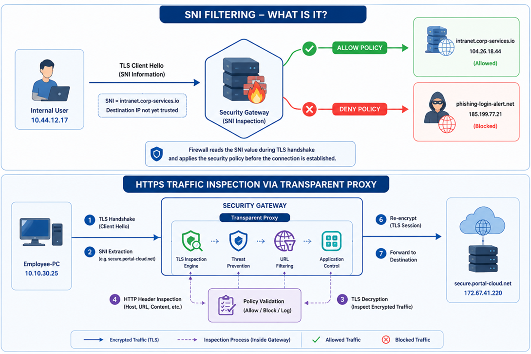
What is SNI filtering?
SNI is an extension of the TLS protocol that allows a client to specify the hostname it wants to reach during the TLS handshake phase.
Even though HTTPS traffic is encrypted, the SNI field is typically visible before encryption is fully established. This allows modern firewalls to inspect the requested domain name and apply security policies without decrypting the entire session.
In this demo, the firewall uses SNI inspection to:
- Allow access to approved domains
- Block connections to suspicious or restricted domains
- Apply filtering policies before the TLS session is completed
This approach is particularly useful in modern cloud and CDN-based environments where multiple domains may share the same public IP address.
For example:
portal.company-internal.io→ Allowedmalware-update-control.net→ Blocked
Instead of relying only on destination IP addresses, the firewall makes decisions based on the requested hostname observed during the TLS handshake.
HTTPS Traffic Inspection via Transparent Proxy
While SNI filtering provides visibility into the destination hostname, deeper inspection may still be required for detecting malicious content, policy violations, or unsafe applications hidden inside encrypted traffic.
To demonstrate this, HTTPS inspection was enabled using a transparent proxy configuration on the Security Gateway.
In this process:
- The client initiates a TLS connection toward a website
- The firewall intercepts the connection transparently
- The gateway performs TLS inspection
- The decrypted HTTP request is analyzed
- Security policies are applied
- The traffic is re-encrypted and forwarded to the destination server
This allows the firewall to inspect:
- HTTP headers
- Host fields
- URLs
- File downloads
- Application traffic
- Malicious payloads
without requiring explicit proxy settings on the client device.
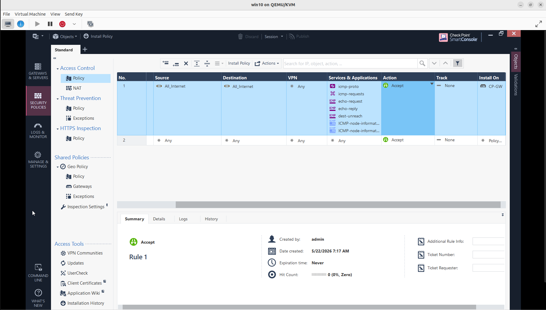
Access Control Policy Configuration
The first stage of the deployment focused on configuring the base access control policy on the Security Gateway. Initial rules were created to permit controlled network communication while allowing ICMP-based connectivity testing between internal and external segments.
The policy configuration demonstrates how Check Point centralizes rule management through the Smart Console interface. Traffic rules are defined using source, destination, service, and action parameters, then compiled and installed on the gateway through the policy installation workflow.
This stage also highlights the separation between policy definition and enforcement, where rules are managed centrally on the Management Server and enforced by the Security Gateway in real time.
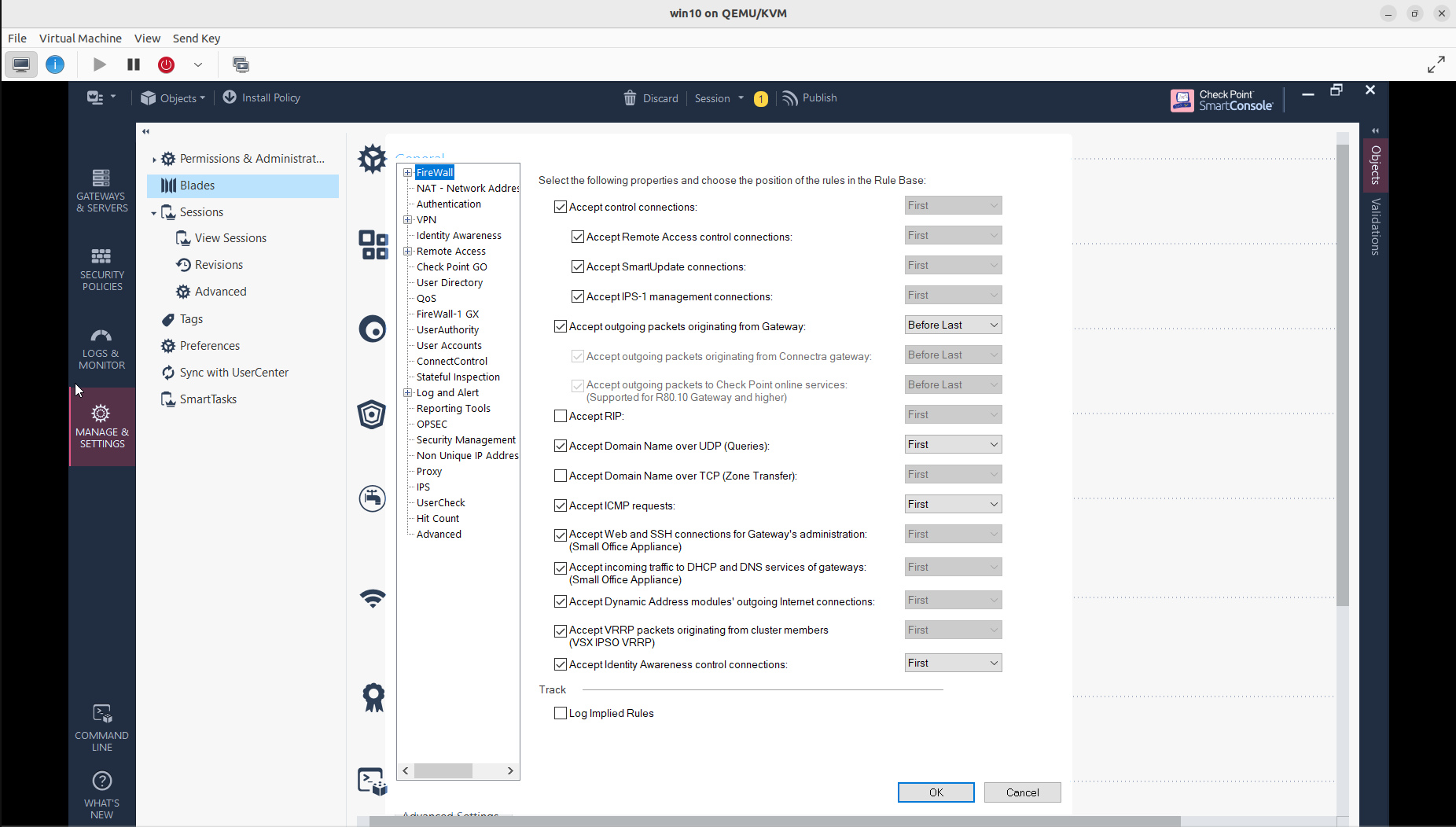
Security Blade Configuration
After establishing the initial access policy, multiple security blades were enabled on the gateway to extend inspection and protection capabilities beyond traditional packet filtering.
The deployment included configuration and activation of features such as:
- Firewall
- NAT
- IPS
- HTTPS Inspection
- Identity Awareness
- Application Control
- URL Filtering
- Threat Prevention
The modular blade architecture used by Check Point allows administrators to selectively enable security functions depending on operational requirements and performance considerations.
This approach provides flexibility while maintaining centralized visibility and policy management across the environment.
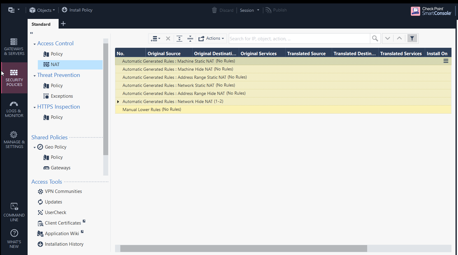
NAT Policy Configuration
The final stage involved configuring NAT policies to provide outbound Internet connectivity for internal enterprise networks.
The Security Gateway translated private internal addresses into routable external addresses before forwarding traffic toward the Internet. This allowed internal systems to securely communicate with external services while preserving network segmentation and internal addressing schemes.
Both automatic and manual NAT rule sections were reviewed during the deployment process to demonstrate how Check Point organizes translation policies inside the Smart Console.
Combined with the access control policy, NAT configuration enabled controlled and monitored communication between internal VLANs and external networks.
One of the most interesting aspects of the deployment was seeing how enterprise firewall platforms differ from traditional router ACL models.
Instead of merely forwarding or blocking packets, the gateway continuously maintains state information about connections and applies decisions based on:
- Session state
- Application context
- TLS metadata
- User identity
- Threat intelligence
- Behavioral inspection
The centralized management model also simplifies policy administration across larger enterprise environments.
Member discussion: